|
Glenn Ramsey
What do we mean by an ``animated hoof model''. Dr Strasser thought up this title and initially I thought it meant animated in the sense of a cartoon or, as is relevant to me, computer generated graphics; however in this context, given that its been translated from German, I figure that animated means lifelike, or to be more technically correct anatomically and biomechanically accurate. But what does that mean?
To be anatomically accurate a model must represent the physical shape of its subject with a high degree of precision. To be biomechanically accurate the model must respond to simulated mechanical forces in the same way that a real hoof would respond. Of course precision and accuracy are always subject to some tolerance and the modeller needs to decide what that should be. Often what's acceptable is dictated by the accuracy of the data available to verify the model. More about validation later.
How will such a model be useful? HMS Davies(1) writes: ``... the present experimental methods of measuring the loading of the hoof are not yet able to provide sufficient information to predict or easily measure the effect of changes in shape on the whole hoof in the living horse. Theoretical modelling of the hoof capsule ... provides a potentially useful way to bypass this problem...''. I like the way Daniel Hofford, CSHS1, puts it: ``The ability to plug in various parameters and watch how they change the stresses on the hoof will be hugely valuable in understanding correct hoof form.''.
To some readers this may seem obvious but I'm going with the principle of "always state the obvious... you may be the first".
The ultimate goal of the model is for it to be able to faithfully simulate the biomechanical behaviour of a normal foot and to be able compare that to the behaviour of different types of abnormal hoof geometry commonly found in domestic hooves. The model might also be useful to predict the mechanical effects of a manipulation of the hoof, such as altering the coronet angle or shortening the bars, on the internal structures where those effects can't be measured. The effect of iron shoes will also be able to be simulated.
The 3d geometrical components of the model may also be useful as a resource for learning hoof anatomy.
In this paper I will discuss some of the techniques used to create biomechanical models and describe how they apply to a hoof model.
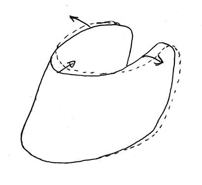
We know in a qualitative sense the general way in which the hoof capsule deforms when it is weighted and unweighted(3,4,2). The deformed shape of a normal2 hoof under physiological normal loads has been described by several authors and it is generally agreed that the toe moves backward at the coronet and the quarters and heels move outward as the hoof becomes weightbearing. This shape is shown in figure 2.1. Some studies have even measured aspects of the deformation of the hoof capsule(6,5) and some studies have modelled the forces in tendons(7,8,9).
There are also numerous studies where the weight on the hoof during locomotion, called the ground reaction force, has been measured.Some studies have investigated the relationship of commonly used indicators of hoof balance, such as hoof pastern axis and commonly used manipulations of these indicators, such as wedges, to hoof pathology(10,11).
The effect of changes in hoof geometry on hoof capsule deformation has been studied in relation to toe angle, toe length, shoeing(6).
The first quantified measurements of hoof deformation by Lungwitz(2) considered aspects of hoof geometry other than toe angle, for example hoof solar length and heel width, indicating the degree of contraction, but since then there are no studies that investigate the effects of contraction on hoof biomechanics. Hoof contraction is however briefly described by Stashak, in Adam's lameness in horses(12), a widely referenced work.
Some studies(13,8)briefly mention that heel pain is a possible contributing factor in some gait abnormalities but do not pursue this line of reasoning.
What we don't know is the the effect of different hoof capsule geometry on the internal forces on the laminae and other soft tissues in the hoof.
Modelling is a process where we attempt to recreate aspects of a physical system in order to study them in a controlled environment or to make predictions about the behaviour of some object in the real world. A model could be a physical model such as the one an architect might make to demonstrate the design of a building or Dr Strasser's bucket model of the hoof(14). Mathematical modelling is a type of modelling where things from the real world are represented by equations that describe how they behave.
An important limitation of a mathematical model is that the equations of mathematical physics are usually only an approximation of the real world.
"As far as the laws of mathematics refer to reality, they are not certain, as far as they are certain, they do not refer to reality." - Albert Einstein
A model of the hoof will simulate the way that the hoof deforms due to forces applied to it. Continuum mechanics is a branch of physics that describes the deformation of materials that are subjected to forces and is the main area of physics that will be used in the hoof model. What is a force? A force is a tangible thing that can be experienced by people but the concept of a force is quite abstract. A force is defined by its effect on a body, it is something that happens to body when its velocity is changed(15). Gravity has the same effect on a body as changing its velocity would have. When a force is applied to an object that's not moving and nothing is in its way the object will accelerate. This effect is described mathematically by Newton's second law F=ma.
Another important principle relevant to continuum mechanics is Newton's 3rd law - for every action there is an equal and opposite reaction. That means that if a body A exerts a force on a body B, an equal but opposite force is exerted by body B on body A(15). The same principle applies if body A and body B are adjacent particles of the same object.
Two things we usually want to know about objects that are subjected to forces are stress and strain. In this context these terms, and a couple of others I'll introduce later, have a very specific meaning that is different to their common usage; strain is a measurement of the amount of deformation in an object or part of an object and it is defined as the change in length divided by the original length; stress is a way of expressing the force within an object that is independent of its size or shape and it is defined in practice as force per unit area.
Since we are interested in the behaviour of the hoof when forces are applied to it, we first need know its original shape and create a mathematical representation of that shape. Usually this is done by defining some sort of coordinate system and representing the object as a collection of points, lines and surfaces within that coordinate system. In a 3 dimensional coordinate system we need to have 3 values to define the position of a point and 6 values to define a straight line between 2 points. Defining curved lines and curved surfaces requires more values.
For biomechanics modelling it is important to accurately represent the geometry of the object being modelled because the properties of biological materials can make the load distribution wildly different for small changes in geometry. The difficulty is that even the simplest of biological objects usually have complex curved surfaces. One way to represent these complex shapes, which is very commonly used in engineering models, is to use more and more straight lines until the model closely represents the real object. You may have seen computer generated graphics that use this technique where the object appears to be made up of many small triangles. This approach works well for objects that have a lot of straight edges but it doesn't represent curved surfaces very well.
For representing curved surfaces an alternative approach is to maintain the technique of representing the object with a collection of small elements but to use elements that have curved edges instead of straight edges. If we choose this method then we need fewer elements to represent the shape to the desired accuracy(16).This is important for doing calculations because it means there will be fewer equations to solve.
A collection of these elements is called a mesh.
To define the geometry of a 3 dimensional object we need to measure it. Possibly this is the easiest part of the modeling process, but it's still is not as simple as it sounds. There are a number of techniques available to measure anatomical geometry and I'll discuss two techniques that I will be using; digitising from an image stack and 3d scanning.
This technique uses images of cross sections of a specimen. If we can obtain a number of cross sectional images at different locations of the specimen then we can select points from each image that follow the outline of the anatomical feature that we are interested in and generate a cloud of points that represent the shape of that feature. In figure 3.1 some points on the edge of the coffin bone have been selected on a transverse cross sectional image of a hoof.
Since these images are 2 dimensional then capturing points from an image only provides 2 out of the required 3 dimensions for each point. The data for the third dimension must be physically measured at the time the image is generated. Once this data is known it is possible to generate a stack of images as shown in figure 3.2.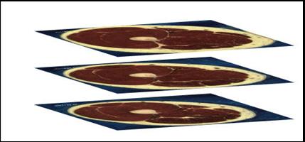
|
There are a few ways to capture anatomical images, some of the relevant ones are magnetic resonance imaging (MRI), computed tomography (CT) scanning and cryosection.
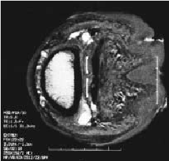
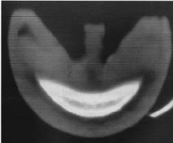
MRI and CT are non invasive techniques that are widely using in medicine for creating sectional images of people. MRI uses a strong magnetic field and CT uses xrays. The resolution of the images created by these techniques depends on the type of machine used to create them and the machines available for my use have limited resolution. An example MRI image of a section through a hoof is shown in figure 3.3 and an example CT image of a section through a hoof is shown in figure 3.4. In both of these images you can see that the edges of anatomical features are indistinct.
|
|
The cryosection method has potential for very high resolution images and has been used to create cross sectional images of a man and a woman by the Visible Human projectThe visible human project http://www.nlm.nih.gov/research/visible/visible_human.html. It involves removing slices from a frozen specimen and taking photographs of the end of the remaining section. Figure 3.5 shows an example of a cryosection image.
You may have guessed by now that this is the method I have employed to capture geometry measurements. To make these images I mounted a frozen cadaver hoof on a thin board to which I glued a wooden ruler as shown in figure 3.6.
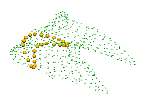
I then cut slices off the specimen using a band saw and took digital photographs of the cut surface using a jig to make sure that the specimen was located in the same place for each photograph.A cloud of points generated from this image set is shown in figure 3.7. Notice that the image slices are not aligned with any of the hoof axes but reflect the the angle that specimen was mounted for slicing.
|
In all of the imaging methods described above the resolution in the axis pointing out of the image is quite poor because the slice thickness is large, and some anatomical details, such as the navicular bone, are smaller than this resolution an can't be accurately measured. This could be greatly improved in the cryosection case by using more sophisticated equipment and that is a future possibility.
3 dimensional scanning uses a laser device to measure the surface shape of an object in 3 dimensions and can be very accurate, possibly in the range of 1/100th of a mm or better depending on the equipment. This is an easy way to capture the surface shape of an object but is obviously not suitable for internal shapes. In the case of a hoof using this technique would require dissection to measure the shape of internal anatomy however it is unavoidable that the soft tissues will become distorted during the dissection process and introduce a large measurement error. A scan of a coffin bone is shown in figure 3.8. This looks impressive but it isn't that useful because although the other bones in the set are available nothing is known about the the shape of the soft tissues or the shape of the hoof capsule.
It may be possible to use this technique after collecting MRI or CT data, to scan only the joint surfaces and bones because these can be easily dissected without damage. This is a technique that I will investigate.
The data points may provide an adequate visual representation of the object but in order for the model to be useful for numerical modelling a mesh is required. The mesh is generated by starting with straight lines and flat surfaces and fitting them mathematically to the data to produce curved surfaces. An initial mesh and a fitted mesh for a simple hoof capsule model are shown in figures 3.9 and 3.10.
The mechanical properties of a material determine how much the material will deform when a given force is applied to it, or more precisely the strain experienced by a material is directly related to the stress in that material. The material property we are most interested in for biomechanics analysis is the property that relates stress to strain called the elasticity or stiffness. When we call a material elastic in this context it refers to the capacity of the material to deform reversibly; that means an elastic material that has deformed because of a force will return exactly to its original shape when the force is removed. The opposite of elastic is plastic. A deformed plastic material will not return to its original shape when the force is removed. Real materials usually display both elastic and plastic behaviour. Examples of mostly elastic materials are glass and rubber; examples of mostly plastic materials are wet potter's clay and soft beeswax.
An interesting and highly relevant property of biological materials is that they have non-linear elasticity and often their elasticity curve is 'J' shaped. What does that mean?
Mathematically the elasticity of a material is defined by the relationship
of stress and strain in that material. The formula relating elasticity,
stress and strain is
![]() , or in English; stress
= elasticity multiplied by strain. We can measure the strain, the
applied force and the relevant dimensions of a piece of a material
and from that the elasticity can be calculated.
, or in English; stress
= elasticity multiplied by strain. We can measure the strain, the
applied force and the relevant dimensions of a piece of a material
and from that the elasticity can be calculated.
For many engineering materials the elasticity can be accurately represented by a constant, in these cases a plot of stress vs strain forms a straight line as shown in the left graph in figure 3.11. For these materials 1 unit of force will produce 1 unit of strain, 2 units of force 2 units of strain and so on, this is called linear elasticity.
For biological materials and especially for soft tissues the stress-strain curve is often 'J' shaped and the material behaviour is described as ``strain-stiffening''. Douglas et al(17) showed that hoof laminar horn has strain-stiffening behaviour and Leach and Zoerb(18) showed the same for hoof wall horn. The 'J' shaped curve means that for small forces the material has low elasticity or in other words can be deformed a large amount by a small force, but as the force increases the amount of strain caused by additional force becomes less and less. This is called non-linear elasticity. You can demonstrate this to yourself by pinching some of your skin and pulling on it. I can pull a piece skin on my arm between my thumb and forefinger and it moves easily for about 20mm, after that it becomes much harder to pull out (and it starts to hurt!).
The relevance of this is that if we were to assume that a biological material has linear elasticity and we used that assumption that to solve some equations then we'd get the wrong answer. So in order for a model to be as accurate as possible the elasticity of the materials needs to be represented by the proper shaped curved.
The non-linear nature of biological materials usually means that the mathematics used to describe them becomes much more complicated, by contrast linear materials have relatively easy mathematics.
Three other characteristics of biological materials that are important are that they are often non-homogeneous, anisotropic or strain rate dependant. Non-homogeneous means that the material may have different properties at different locations for example it may be stiffer in one location than another. Cancellous bone tissue, located inside the bone, is an extreme example, its stiffness can vary by [see Iain]. Anisotropic materials have different properties in different directions. Most woods are anisotropic because they are stiffer and stronger with the grain than across the grain. Strain rate dependant means that the elasticity depends on whether the load is applied slowly or quickly.
The easiest case to model is where the material is linear elastic, homogeneous, isotropic and not strain rate dependent, for example steel or concrete. Unfortunately the biological materials in the hoof have many of the ``difficult'' properties. Sometimes it is acceptable to simplify a situation by pretending that a mildly non-linear material is actually linear, sometimes you can get away with that, sometimes not.
The elasticity of hard tissues such as bone and maybe hoof horn can be measured using indentation testing. In this technique the force required to drive an indenter into a sample of material and the corresponding extension is measured.
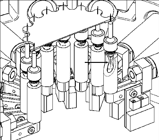
The elasticity of soft tissue is very difficult to measure. One technique that has been successfully applied to measure the elasticity of materials such as non-homogeneous membranes and skin involves measuring the forces and displacements in a tissue sample in 2 dimensions(19). In this technique strains on a membrane mounted in a test rig are measured in 2 dimensions using an optical technique and forces are measured using force transducers located around the perimeter of the sample.
|
Soft tissues sometimes have markedly different properties in vivo (living) and in vitro (dead) this presents an additional measurement challenge.
The continuum mechanics equations define the relationships between material properties, stress and strain.
The problem with the continuum mechanics equations is that for any but the simplest shapes they are mathematically complex and difficult or impossible to solve analytically. By analytically I mean using mathematical relationships to transform the equations from something unwieldy to something that can be used to obtain a real answer. By simply shaped objects I mean objects like squares, circles, disks, ellipses and so on, these are objects where the shape can be described by a relatively simple equation. The ``easy'' shapes are mainly 2 dimensional and anything 3 dimensional is mostly too hard to solve. Fortunately for us many real world scenarios can be adequately approximated by a 2 dimensional case and that is one of the reasons why bridges don't fall down... very often.
Most engineering materials exhibit small strains under their design loads and the continuum mechanics equations can be simplified to take advantage of this fact. Biological materials on the other hand usually exhibit large strains in response to physiologically normal loads and the simplification is not valid for them. A further complication arises from the 'J' shaped stress-strain curve and that makes the equations even more difficult to solve.
Dealing with the equations of complex 3 dimensional shapes, non-linear material properties and large deformation continuum mechanics is where numerical analysis and the finite element method come to the rescue.
The finite element method (FEM) is a mathematical technique that can be used to solve the equations of continuum mechanics. It is particularly suitable for solution by computers and is widely used in this way. In the FEM a geometrically complex object is divided into many small geometrically simple parts, called elements, and a solution is obtained for each of the elements. Since the elements are geometrically simple then obtaining the solution for each of them individually is easy, but since there are normally a lot of elements and each one influences its neighbours you don't want to do this by hand (but they make you do it in the exam and it takes a lot of scribbling to get a solution for a pitifully small number of elements!).
In mathematics generally when something is linear it is relatively easy to obtain a solution, non-linear problems are much harder or sometimes impossible to solve analytically. Using numerical techniques a very close approximation to the solution of non-linear equations can usually be obtained.
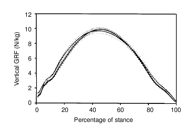
It's not too hard to measure external effects such as ground reaction force using a force plate or instrumented hoof boot and this has been done in several studies.
|
There is one issue that may make the estimation of the load a little more difficult for a realistic simulation and that is because it is probable in an unshod hoof that the hoof capsule deforms and redistributes the load unevenly upon ground contact. The effects of the ground deforming under the hoof will also have a significant effect on the distribution of force on the hoof capsule. Fortunately it is possible to include these effects in a model.
Once we have a detailed 3 dimensional description of the hoof geometry, including the capsule, coffin bone and soft tissues and we know the material properties for each of the tissues then we can put together a relatively complex system of equations that describes the strain in the hoof. Adding in some extra data to define the forces on the model then allows us to find a solution to those equations. Fortunately most of that can be done with the aid of software, but it's still far from trivial.
Once the system of equations has been set up they can be solved by computer software using the finite element method. The answer we are solving for is the strain (deformation) field in each of the hoof tissues. Once we have that then we can get the software to also find the stresses (load per unit area).
The Bioengineering Institute has developed a method of creating patient specific models by customising a generic model to fit a relatively small number of measured points. The technique involves embedding the generic model's mesh inside a host mesh and because of this it is known as host mesh fitting. In a hoof model this technique allows a generic model to be easily reshaped to represent and allow the study of many possible hoof deformities.
Creating an accurate biomechanical model is not a trivial task, even doing the easy part; defining the geometry; can be very time consuming. A geometric model of a sheep hind leg took one person about 6 months to complete and a geometric model of the human knee took one person about 1 year to complete. If the model is to be used for mathematical analysis then it is important to define the geometry in a way that is suitable for this purpose and that takes more time. The cardiac models developed by the Bioengineering Institute at The University of Auckland are the result of more than 2 decades of research by a team of people.
A model is not much use unless we know how accurately it represents its subject. Validation means to determine how accurately the model represents its subject. In general this requires taking some measurements from the real world, simulating the scenario with the model and then comparing the results.
It is important, if possible, to validate any biological model using data from living rather than dead organisms. This is because the properties of some types of tissue change significantly after the death of the organism. Apart from the ethical issues involved, for the hoof it is also a difficult technical problem. Using invasive techniques such as surgical implanting measurement devices might significantly change the way that the animal moves, while the available non-invasive techniques can only reliably measure the surface deformation of the capsule or the skin.
In the hoof model we are initially interested in the deformation of the hoof capsule and fortunately there are a number of techniques available to measure it. I'll briefly introduce three techniques; strain gauges, photo-elasticity and optical measurement, that have been used successfully on live horses.
A strain gauge is a tiny electrical component that must be firmly attached to the surface where a measurement is desired. The gauge requires an electrical connection to a strain gauge amplifier, this seems quite cumbersome but it has been successfully used on live horses[ref Thomason]. A disadvantage of this technique is that it only measures the strain at the location of the gauge so the number of data points available is limited.
Photo-elasticity is property of certain specialised transparent plastics. If the plastic is deformed then when viewed through a polarising light filter areas of similar strain are visible as coloured fringes on the plastic surface. This technique has been used on live horses(5) but it is mostly only useful to show a strain distribution because it is difficult to calibrate to obtain quantified values. Even though making quantified measurements is difficult this is a very useful technique because it shows the strain over the whole hoof at once.
Optical measurement involves attaching highly visible markers to the hoof capsule and capturing images using one or more of cameras[ref Burn]. The images are then compared and the strain measured from the differences in the images.
There have been a few attempts at finite element models of the hoof(22,20,21) but only one study so far has attempted validation(22). All of these models included only the hoof capsule and they used commercial finite element analysis software intended for analysis of engineering materials.
The study where validation was performed showed that the model gave very poor results in terms of the magnitudes of strains predicted but was able to predict the relative strains, meaning that it could predict the location of the maximum and minimum strains but not the magnitude.
Sources of error in this type of model are potentially introduced if the models used a linear mesh, linear elastic material properties and small strain continuum mechanics equations. An additional and easily overlooked factor is the possible existence of a tension preload in the capsule.
At this point it's all future development however during the course of this research project the intention is to create a model for investigating the effects of forces applied to different types of hoof shapes. Other areas where a model could be developed, building on the initial work, include vibration analysis and blood flow analysis.
This document was generated using the LaTeX2HTML translator Version 2K.1beta (1.48)
Copyright © 1993, 1994, 1995, 1996,
Nikos Drakos,
Computer Based Learning Unit, University of Leeds.
Copyright © 1997, 1998, 1999,
Ross Moore,
Mathematics Department, Macquarie University, Sydney.
The command line arguments were:
latex2html -no_subdir -split 0 -show_section_numbers /tmp/lyx_tmpdir32021QpDzgJ/lyx_tmpbuf0/hoof-modelling-paper.tex
The translation was initiated by Glenn Ramsey on 2004-02-01